Literature
Technical Tips & FAQs
Electronic interface Functionality on CA9 Contactors
QUESTION:
The ‘ EI ‘ electronic interface function? And – how does it work on the CA9 contactors?
Are there options to use / or not use the ‘ EI ‘ electronic interface functionality on the CA9 contactor?
ANSWER:
The function of a ‘ EI ‘ electronic interface feature allows operation of the contactor to be controlled by separate logic signals from, for instance, a PLC. Use of logic control requires a steady supply voltage on A1 and A2 within the rated voltage range, as described for codes 24W, 48W, 120W, 480W. The function of the logic control signal will no longer be guaranteed when the supply voltage is removed.
 The logic control signals are operated with 24V DC. There are two control signals (ON and OFF_N) and a common reference (COM). For the control signals, the function is guaranteed from 15V DC (6mA) to 33V DC (20mA).
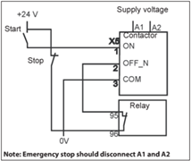
The contactor is closed by a common signal ON and opened by removal of control signal from OFF_N. The functions are described in the provided diagram.
- “ 1 “ means 24V DC between the control signal and COM.
- “ 0 “ means no voltage between the control signal and COM.
Minimum control signal pulse length for opening and closing is 10ms. To connect the PLC interface, use cable dimension of max 1.5mm².
CA6 vs. CA9
The CA9-__-EI electronic interface functionality is equipped differently within the CA9 range of contactors.
On the lower range of CA9 contactors between the amps of 116A...370A, there is a selection option to purchase the contactor with or without the integrated "EI" functionality.
CA9-116...370-EI-11-* inclusive with ‘ EI ‘ electronic interface feature
CA9-116...370-11-* without ‘ EI ‘ electronic interface feature
It is important to know that the selection of a CA9-116...370-EI contactor requires the ‘ EI ‘ function to be utilized and the device would be expecting an input from separate logic control signals.
The higher range of CA9 contactors at 400A and larger have the ‘ EI ‘ electronic interface feature integrated into the device as a standard. These contactors at CA9-400-EI and larger have the potential to energize the coil by either one of two ways:
- Control by switching voltage on A1 and A2
- Control with separate logic control signals
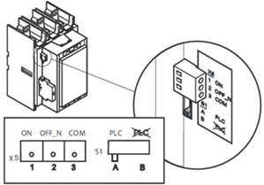 Selection of control method is done with switch S1. (see provided illustration)
Control by switching voltage on A1 and A2 (switch S1 in position B default factory setting)
Operation of CA9 contactors can be done as with conventional contactors by applying and removing voltage on A1 and A2.
Control with separate logic control signals (switch S1 in position A)
Use of the logic control signals also require a steady voltage on terminal A1 and A2 within the operational limits. Minimum pulse length for opening and closing is 7ms. The function of the logic control signals will no longer be guaranteed when the voltage on A1 and A2 is removed. The logic control signals operate with 24V DC and consist of two control signals (ON and OFF_N) and a common reference (COM). The contactor is closed by a control signal ON and opened by removal of control signal from OFF_N.
The CA6-__-EI contactors with electronic coils draw a large amount of inrush current during start up when using an interposing relay to energize A1 coil terminal (assuming you are NOT using the PLC interface). During the inrush time, the coil will draw 40 amps for 1 millisecond, and 20 amps over a 20 millisecond time period. The total inrush time period is about 80 milliseconds before the contactor coil draws its sealed current.
EXAMPLE: We recommend wiring a CA6-180-EI-11-24D DC contactor for PLC control. The signal required is 24V DC, 15 mA max. If you must use an interposing relay, use the CA6-180-L22-24D contactor which uses a conventional DC coil. Inrush is 540 watts (22 amps of inrush). The interposing relay would have to be a CA7-30E-10-24E contactor or larger.
Categories: Contactors, Starters
1967